37 Results
View results:
Sort by:

If you want to use a pure surface model, for example, when determining the internal forces and moments, but the structural component is still designed on the member model, you can take advantage of a result beam.
In the case of a reinforced concrete model represented as a mixed structure consisting of surface and member elements, the design is carried out in different modules.

The "4.0 Results - Summary" table displays the infinity norm at the end of the load case results. The norm is used to estimate the largest eigenvalue of a structure. The largest eigenvalue of a structure is estimated by numerical analysis, as accurate determination can be very time-consuming.

In RF‑TENDON and RF‑TENDON Design, you can review and adjust the code‑dependent factors, calculation parameters, and calculation methods using the "Code" button. You can display the settings and adjustment options according to a chapter of a code, selecting the "Grouping" option in the dialog box.
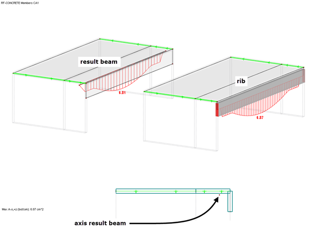
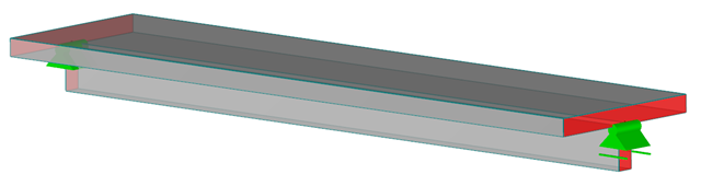
Although the design of downstand beams is usually carried out on a member model, a result beam can be used to perform the design on a model with only surfaces.

Once you have determined the final tendon geometry in RF‑TENDON, exporting the model to a CAD program can be useful. For this purpose, the module includes the option to export the file in the .dxf file format. You can select the export function by right-clicking the workspace. After selecting the DXF format and the storage location, additional settings can be made.

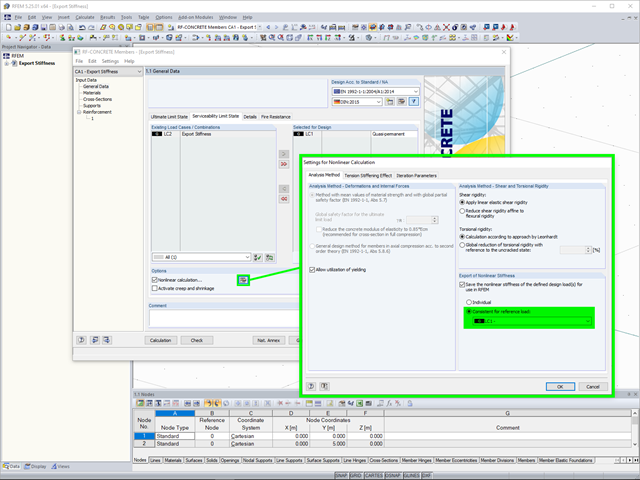
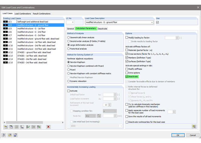
If nonlinear effects - such as failing supports, foundations, member nonlinearities, or contact solids - are used in the model, you can deactivate them in the global calculation parameters.
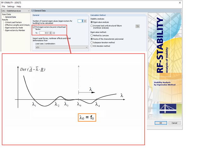
The function, which is also known as shifting, allows you to calculate critical load factors beyond a user‑defined initial value. Determination of the critical load factors is usually done from the smallest to the greatest critical load factor.

The determined values for the influence ordinates are displayed as decimal numbers with up to six decimal places by default. This is usually sufficient for the influence lines of internal forces.
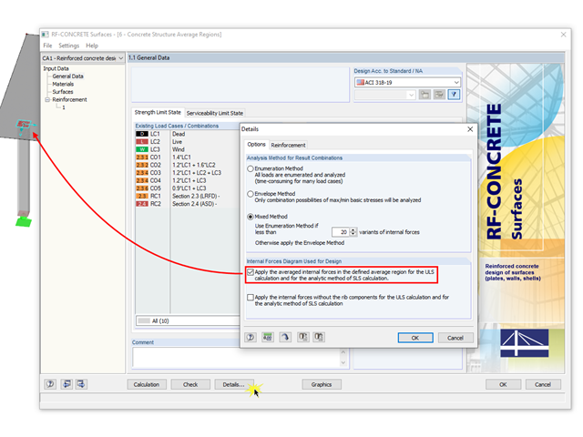
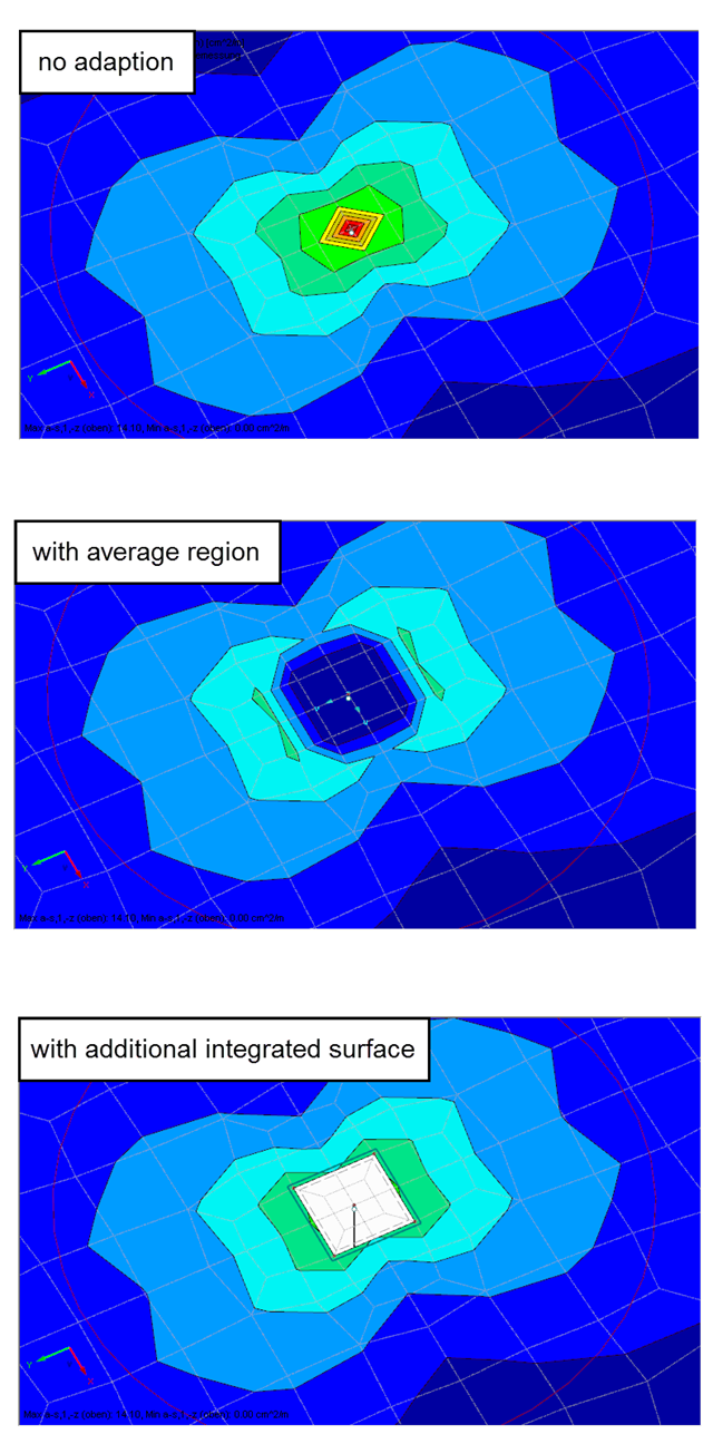
The averaged internal forces from the previously defined average regions can also be used for designing concrete surfaces. To do this, click [Details] in RF‑CONCRETE Surfaces, then select the corresponding check box. This function is accessible only if you previously defined an average region.
The Views Navigator in RFEM 5 and RSTAB 8 provides many options for setting the screen views.

According to Book 631 of the DAfStb (German Committee for Structural Concrete), Chapter 2.4, the structural behavior of ceilings changes if their continuous support by walls is interrupted in areas of openings. Depending on the length of the opening area and the plate thickness, measures are necessary regarding the analysis of the ceiling in the area of the opening.
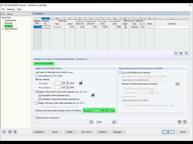
Eurocode 2 provides two ways to perform a crack width design. On one hand, the crack width design according to 7.3.3 can be performed without direct calculation by means of tables for the limitation of the member spacing and diameter. On the other hand, the crack width wk can be determined directly according to 7.3.4 and compared to a limit value.
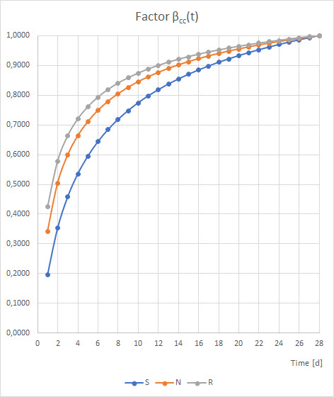
When determining the minimum reinforcement for the serviceability limit state according to 7.3.2, the applied effective tensile strength fct,eff has a significant influence on the determined amount of reinforcement. The following article gives an overview about determining the effective tensile strength fct,eff and the input options in RF-CONCRETE.

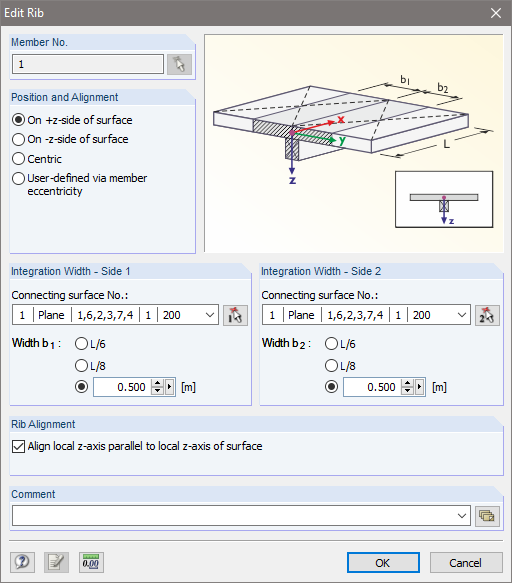
When modeling a reinforced concrete rib with a masonry wall above, there is the risk that the rib is underdesigned if the structural behavior of the masonry is not correctly considered and the connection between the masonry wall and downstand beam is not modeled sufficiently accurately. This article deals with this issue and shows the possible modeling options of such a structure. In this example, the reinforcement is determined only from the internal forces and without secondary minimum reinforcement.

Different methods are available for calculating the deformation in the cracked state. RFEM provides an analytical method according to DIN EN 1992-1-1 7.4.3 and a physical-nonlinear analysis. Both methods have different features and can be more or less suitable depending on the circumstances. This article will give an overview of the two calculation methods.
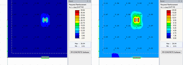
RFEM offers different options for the graphical display of results that have been determined in RF-CONCRETE Surfaces. This article gives an overview of these options.

The secondary reinforcement according to DIN EN 1992-1-1 9.2.1 is used to ensure the desired structural behavior. It should avoid failure without prior notification. The minimum reinforcement has to be arranged independently of the size of the actual loading.
Singularities occur in a limited area due to the concentration of the stress-dependent result values. They are conditioned by the FEA methodology. In theory, the stiffness and/or the stress in an infinite size concentrate on an infinitesimally small area.
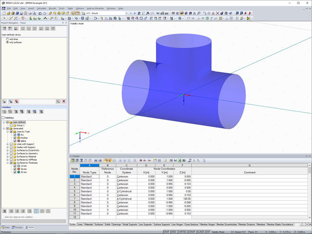
RFEM and the RF-CONCRETE add-on modules provide various options for the deformation analysis of a T-beam in the cracked state (state II). This technical article describes the calculation methods (C) and modelling options (M). Both the calculation methods and the modelling options are not limited to T-beams, but will be only explained using an example of this system.

According to Clause 7.3.2 (2), standard DIN EN 1992-1-1 requires: "In profiled cross‑sections like T‑beams and box girders, the minimum reinforcement should be determined for the individual parts of the section (webs, flanges)." In the case of a floor beam with a T‑section, the minimum reinforcement should be determined for both flanges and the web if the corresponding partial cross‑sections are in the tension area. Image 01 shows the division into partial cross-sections.
![Parameters of Effective Slab Width (Figure 5.3 [1])](/en/webimage/009561/2419376/01-en-png.png?mw=640&hash=c76563b459152b19c98197ea6ba342be89d9a5bc)
In the case of combined FEM structures (surface and member elements) as well as folded plate structures, it is possible to attribute a beam structure for the design on a member to a fictitious T-beam cross-section, whose geometry depends on the effective width. When using the "Rib" member type in RFEM, the stiffness is represented by a slab component (surface element) and a web component (member element). This approach has some design specifics that are explained in this article.
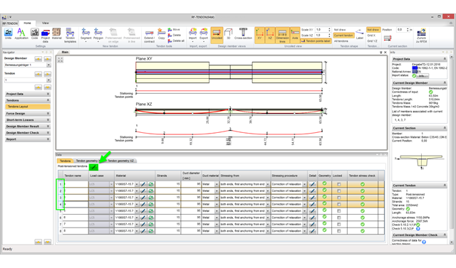
With program version RFEM 5.06, you can edit several tendons in the RF‑TENDON add‑on module simultaneously. To do this, it is necessary to select the corresponding tendons in the tendon arrangement table.
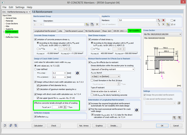
As of program version 5.06, you can use the option to adjust the effective concrete tensile strength fct,eff,wk at the time of cracking. At the start of the SLS design, the program checks whether the internal forces can cause cracks in the concrete. For this, the effective concrete tensile strength at the time of cracking is applied. You can adjust the strength via the factor. The calculation details display the adjusted value.
Downstand beams or T-beams are often used in reinforced concrete structures. In contrast to the previous representation and calculation options where, for example, a downstand beam was considered as a fixed support and the determined support reaction was applied to a separate member structure using a T-beam section, the ultimate structural FEA software like RFEM allow you to consider the structure as a whole and thus achieve a more precise analysis.
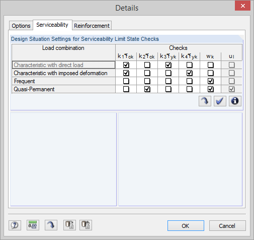
With program version 5.06, RF‑CONCRETE Surfaces and RF‑CONCRETE Members perform serviceability limit state designs automatically according to the design situation of the calculated load cases, load combinations, and result combinations.
The current state of the development of finite element analysis software and computer technology allows for the calculation of more complex structure. More and more frequently, FE calculations are performed on the entire model. In this context, certain practical construction problems may appear. One of these problems is the consideration of a construction process in the model.
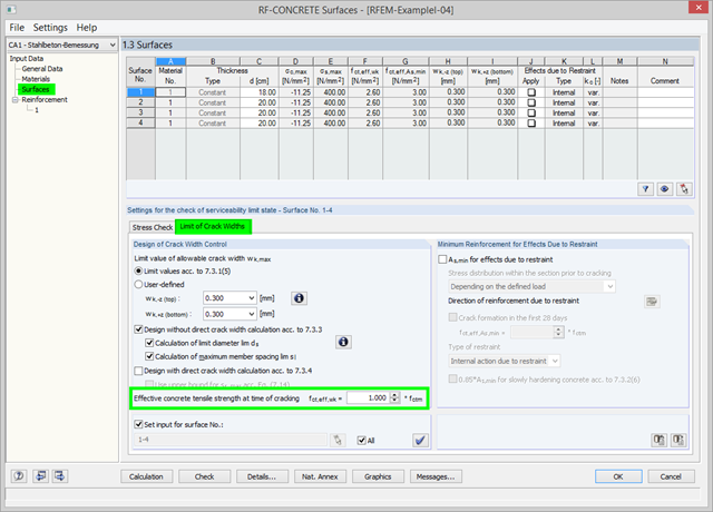
As of RFEM Version 5.06, there is the option in RF‑CONCRETE Surfaces to adjust the effective concrete tensile strength at the time of cracking. At the start of the SLS design, the program checks whether the internal forces can cause cracks in the concrete. For this, the effective concrete tensile strength at the time of cracking is applied. You can adjust the strength via the factor. The calculation details display the adjusted value.
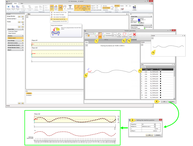
In RF-TENDON, you can import tendon geometry from a DXF file. Thus, you can use basically any tendon geometry.
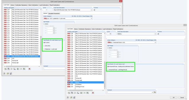
If you select the combinatorics according to EN 1990 + EN 1991‑2 and define a load case in action category gr1a, gr2, or gr5, you have to additionally define in the program which load model should be taken as a basis for the load case. This information is crucial for defining combination rules for automatic combinations according EN 1990 + EN 1991-2. In the gr1a category, you can select TS (LM1), UDL (LM1), or pedestrian and cycle track, for example. TS (LM1) is preset by default. In the gr2 category, you can select breaking and acceleration forces or centrifugal forces as a specification.